Data Aquisition and Trigger System
With a bunch-crossing frequency of 40 MHz and about 25 interactions per crossing in the low-luminosity phase, a very sophisticated trigger and data acquisition system is required to select the very rare processes, of main interest to physicists.
The ATLAS Trigger and Data Acquisition system (TDAQ) is based on a multi-level selection process and a hierarchical acquisition tree. The system consists of a combination of custom made electronics and commercial products. It is required to reduce the data rate by a factor of 105 from the initial collision frequency of 40 MHz to a rate of events written to mass storage of about 200 Hz, and to provide a total data throughput in the range of Terabit/s. The system is designed to take maximum advantage of the physics nature of events. A Region-of-Interest (RoI) mechanism is used to significantly reduce the amount of data needed to calculate the trigger decisions. The functional elements of the ATLAS TDAQ system can be divided logically into a fast first level trigger (Level 1), a High Level Trigger system and a Dataflow system.
Level 1 Trigger
The first trigger level is a hardware based system that reduces the event rate from 40 MHz to about 75 kHz (later on an upgrade to 100 kHz is projected) within a fixed latency of less than 2.5 μs. The Level 1 (LVL1) system is composed of three parts: the Calorimeter Trigger (L1Calo), the Muon Trigger (L1Muon) and the event-decision part implemented in the Central Trigger Processor (CTP).
Events in the calorimeter system are digitized by the Preprocessor which also performs bunch-crossing identification. A Cluster Processor identifies e−/γ and hadron/τ candidates using a sliding-window algorithm. The transverse energy ET of the candidates is discriminated against up to 16 programmable thresholds. A Jet/Energy Processor identifies jet candidates and discriminates their ET values against eight programmable thresholds. It also evaluates several global energy sums (e.g. missing ET ). The L1Calo sends multiplicities of the e−/γ, hadron/τ and jet candidates as well as the global energy information to the Central Trigger Processor.
The algorithms of the muon trigger are based on hit coincidences in different stations within a geometrical track whose width is related to the pT threshold applied. The coincidence logic allows up to six thresholds to be applied. L1Muon forwards the multiplicities of muon candidates for each threshold to the CTP.
The Central Trigger Processor combines the input signals logically to up to 256 different trigger types, according to a trigger menu. It applies deadtime and prescale factors to each trigger. The L1A signal is a logical OR of all triggers and is distributed to the sub-detectors via TTC10 partitions including one Local Trigger Processor (LTP) each. A BUSY tree allows the sub-detectors to block the generation of LVL1 triggers.
During the latency of the Level 1 trigger selection algorithms the complete event data is kept in the pipeline memories of the sub-detector front-end electronics. Only data of events selected by the LVL1 system is then transferred to the ROBs11, where it is temporarily stored and provided to the High Level Trigger system on request. The components of the Level-1 system also send information regarding the trigger type and the η and φ coordinates of the objects, that caused the event to be accepted, to the Region-of-Interest Builder (RoIB) via an optical connection. The RoIB collects the Region-of-Interest information from the Level-1 system and passes it to the Level-2 system. The Region-of-Interest Builder is implemented as a custom VMEbus12 system consisting of multiple input and builder cards controlled by a SBC13.
High Level Trigger and Dataflow
The second and third trigger levels, Level-2 trigger and Event Filter (EF), together form the High Level Trigger (HLT) system. It is running on farms of commercially available PCs, executing an offline-like software package called HLT Selection Software (HLTSSW). This software is based on the ATLAS offline Athena framework. During operation of the Level-2 and EF algorithms the event data is stored in the ROBs. Events can be rejected at any point in the decision process and are only deleted from the ROBs if rejected or after fully building the event upon acception by the Level-2 trigger.
The Level-2 trigger system is designed to provide a data reduction factor of 20 - 30 within a latency of ≈ 10 ms. As it must work at the Level-1 accept rate, and required latency is to be minimized, the algorithms used provide modest precision. They request data from the ROBs identified from the Region-of-Interest. Therefore typically only about 2% of the event data is processed, minimizing network traffic. The expected rate of events accepted by Level-2 is about 3.5 kHz.
If an event is accepted by the Level-2 trigger algorithms the Data Flow Manager (DFM) assigns the event to the event-building nodes (Sub-Farm Interface, SFI ) according to load-balancing criteria. One SFI per event collects the full event data from the ROBs and fully builds the event before passing it to the Event Filter. More sophisticated reconstruction and trigger algorithms, adapted from the offline reconstruction software, process the event with an average treatment time of ≈ 1 s. Events selected by the EF are then sent to mass storage by the Sub-Farm Output (SFO) node. An event rate of 200 Hz is expected after the EF. Given a mean ATLAS event size of about 1.6 MB, data is written to mass storage at a rate of about 300 MB/s.
Online Software
The Online Software system is responsible for configuring, controlling, and monitoring the TDAQ system. It provides the services that enable the TDAQ and detector systems to start up and shut down. It is also responsible for the synchronization of the the entire system and the supervision of processes. During data taking, access is provided to monitoring tasks, histograms produced in the TDAQ system, and the errors and diagnostics messages sent by different applications. One or more user interfaces display the available information and enable the user to configure and control the TDAQ system, including transitions between the states of the TDAQ system described below.
TDAQ States
The high-level operation of the experiment, and the relationships between the main systems (the detector itself, the LHC machine, and the TDAQ system) are described in terms of logical and functional states. A given state determines what operations are allowed while the system is in that state. For example, the operator will not be allowed to turn off high voltages while the detector is taking data, whereas he will be allowed to stop data taking. Three principal states can be used to define the main operations of the TDAQ system:
- Initial. This state represents the case when TDAQ sub-systems are started up but idle. It is the earliest state in which it is possible to send commands directly to the TDAQ control elements. The only operations which are allowed are those which bring the overall system to a situation where data-taking can be performed. The TDAQ system may also revert to this state in order to re-initialize significant parts of ATLAS.
- Configured. In this state the TDAQ system is ready, provided other conditions related to the state of the detector or the LHC machine are met, to initiate a data taking session. This means that the various components have been properly initialized. In some initialization procedures, the configured state may be reached by passing through one or several sequentially-dependent intermediate states, for example, loading different layers of software into processors, configuring interdependent components, and so on.
- Running. In this state the TDAQ system is data-taking
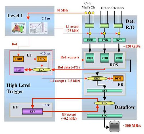
ATLAS trigger and data acquisition architecture. Thinner arrows indicate the flow of control messages, thicker ones indicate the flow of data fragments. The black arrows show the main data path.